Data analysis
Types of data files
Calibration files and directories - overview
(See Calibration for an overview on calibration.)
Calibrations may be saved as:
- A calibration directory (see below)
- An .xml file with just the calibration.
Additionally, calibrations may be saved in:
- .h5 files
- .xml files that also include stimulus or trajectory information.
All calibration sources can save the camera matrix for the linear pinhole camera model for each camera, the scale factor and units of the overall calibration, and the non-linear distortion parameters for each camera.
Calibration directories
To provide compatibility with the Multi Camera Self Calibration Toolbox by Svoboda, et al, the calibration directory includes the following files:
- calibration_units.txt - a string describing the units of the calibration
- camera_order.txt - a list of the flydra cam_ids
- IdMat.dat - booleans indicating the valid data
- original_cam_centers.dat - TODO
- points.dat - the 2D image coordinates of the calibration object
- Res.dat - the resolution of the cameras, in pixels
- camN.rad - the non-linear distortion terms for camera N
The Multi Camera Self Calibration Toolbox (written in MATLAB) adds several more files. These files contain the extrinsic and intrinsic parameters of a pinhole model as well as non-linear terms for a radial distortion. flydra_mainbrain loads these files and sends some of this information to the camera nodes. Specifically the files are:
- TODO - (Need to write about the files that the MultiCamSelfCal toolbox adds here.)
Image files
- .fmf (Fly Movie Format) files contain raw, uncompressed image data and timestamps. Additionally, floating point formats may be stored to facilitate saving ongoing pixel-by-pixel mean and variance calculations.
- .ufmf (micro Fly Movie Format) files contain small regions of the entire image. When most of the image is unchanging, this format allows reconstruction of near-lossless movies at a fraction of the disk and CPU usage of other formats.
Tracking data files
Tracking data (position over time) is stored using the HDF5 file format using the pytables library. At a high level, there are two types of such files:
- raw 2D data files. These contain
/data2d_distortedand/cam_infotables. Throughout the documentation, such files will be represented asDATAFILE2D.h5.- “Kalmanized” 3D data files. These contain
/kalman_estimatesand/ML_estimatestables in addition to a/calibrationgroup. Throughout the documentation, such files will be represented asDATAFILE3D.h5.
Note that a single .h5 file may have both sets of features, and thus may be both a raw 2D data file in addition to a kalmanized 3D data file. For any data processing step, it is usually only one or the other aspect of this file that is important, and thus the roles above could be played by a single file.
Stimulus, arena, and compound trajectory descriptions
XML files may be used to specify many aspects of an experiment and analysis through an extensible format. Like Tracking data files, these XML files may have multiple roles within a single file type. The roles include
- Arena description. The tags
cubic_arenaandcylindrical_arena, for example, are used to define a rectangular and cylindrical arena, respectively.- Stimulus description. The tag
cylindrical_post, for example, is used to define a stationary cylinder.
Because the format is extensible, adding further support can be done
in a backwards-compatible way. These XML files are handled primarily
through flydra_analysis.a2.xml_stimulus.
Predefined analysis programs
(TODO: port the list of programs from the webpage.)
Automating data analysis
The module flydra_analysis.a2.flydra_scons provides definitions that may
be useful in building SConstruct files for scons. Using scons allows
relatively simple batch processing to be specified, including the
ability to concurrently execute several jobs at once.
Source code for your own data analysis
The module flydra_analysis.a2.core_analysis has fast, optimized
trajectory opening routines.
Data flow
![digraph G {
size ="6,4";
TwoDee -> da;
cal -> da;
motion_model -> da;
da -> ML_estimates;
da -> kalman_estimates;
ML_estimates -> smoothed_kalman_estimates;
motion_model -> smoothed_kalman_estimates;
da [label="data association & tracking (flydra_kalmanize or flydra_mainbrain)"];
TwoDee [label="2D observations"];
cal [label="calibration"];
motion_model [label="dynamic model"];
kalman_estimates [label="kalman_estimates (in .h5 file)"];
ML_estimates [label="ML_estimates (in .h5 file)"];
smoothed_kalman_estimates [label="smoothed kalman estimates [output of load_data(use_kalman_smoothing=True)]"];
}](_images/graphviz-9283004ff922486ce26f248ad5d8c17f5d4c0a6a.png)
Extracting longitudinal body orientation
See also Estimating orientations with flydra.
Theoretical overview
Our high-throughput automated pitch angle estimation algorithm consists of two main steps: first, the body angle is estimated in (2D) image coordinates for each camera view, and second, the data from multiple cameras are fused to establish a 3D estimate of longitudinal body orientation. We take as input the body position, the raw camera images, and an estimate of background appearance (without the fly). These are calculated in a previous step according to the EKF based algorithm described in the flydra manuscript.
For the first step (2D body angle estimation), we do a background subtraction and thresholding operation to extract a binary image containing the silhouette of the fly. A potential difficulty is distinguishing the portion of the silhouette caused by the wings from the portion caused by the head, thorax, and abdomen. We found empirically that performing a connected components analysis on the binary image thresholded using an appropriately chosen threshold value discriminates the wings from the body with high success. Once the body pixels are estimated in this way, a covariance matrix of these pixels is formed and its eigenvalues and eigenvectors are used to determine the 2D orientation of luminance within this binary image of the fly body. To add: a description of the image blending technique used with high-framerate images for ignoring flapping wings.
From the N estimates of body angle from N camera views, an estimate of the 3D body axis direction is made. See Estimating orientations with flydra for a description of this step.
Practical steps
Estimating longitudinal body orientation happens in several steps:
- Acquire data with good 2D tracking, a good calibration, and .ufmf movies in good lighting.
- Perform tracking and data assocation on the 2D data to get 3D data using flydra_kalmanize.
- Run flydra_analysis_image_based_orientation to estimate 2D longitudinal body axis.
- Check the 2D body axis estimates using flydra_analysis_montage_ufmfs to generate images or movies of the tracking.
- Finally, take the 2D orientation data and make 3D estimates. Nowdays the best way to do this is with flydra_analysis_orientation_ekf_fitter, as described here. (The old way was another run through the tracker and data association using the flydra_kalmanize program again.) This 2D to 3D stage is covered in the estimating orientations with flydra section.
An example of a call to
flydra_analysis_image_based_orientation is: (This was
automatically called via an SConstruct script using
flydra_analysis.a2.flydra_scons.)
flydra_analysis_image_based_orientation --h5=DATA20080915_164551.h5 --kalman=DATA20080915_164551.kalmanized.h5 \
  --ufmfs=small_20080915_164551_cam1_0.ufmf:small_20080915_164551_cam2_0.ufmf:small_20080915_164551_cam3_0.ufmf:small_20080915_164551_cam4_0.ufmf \
  --output-h5=DATA20080915_164551.image-based-re2d.h5
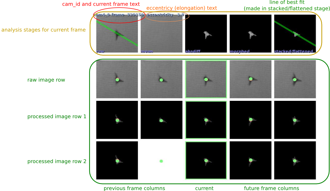
You can use the --save-images option to the flydra_analysis_image_based_orientation command. You will then generate a series of images that look like this:
When calling flydra_analysis_montage_ufmfs, you’ll need to use at least the following elements in a configuration file:
[what to show]
show_2d_orientation = True
An example output from from doing something like this is shown here:
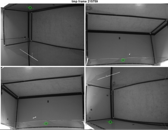
The critical issue is that the body orientations are well tracked in 2D. There’s nothing that can be done in later processing stages if the 2D body angle extraction is not good.