Fusing 2D orientations to 3D
Flydra uses an extended Kalman filter (EKF) and a simple data
association algorithm to fuse 2D orientation data into an a 3D
orientation estimate. The program
flydra_analysis_orientation_ekf_fitter is used to perform
this step, and takes, amongst other data, the 2D orientation data
stored in the slope column of the data2d_distorted table and
converts it into the hz_line* columns of the
ML_estimates table. (The directional component of these
Pluecker coordinates should be ignored, as it is meaningless.)
See smoothing orientations for a description of the step that chooses orientations (and thus removes the 180 degree ambiguity in the body orientation estimates).
The following sections detail the algorithm used for the finding of the hz_line data.
Process model
We are using a quaternion-based Extended Kalman Filter to track body orientation and angular rate in 3D.
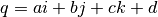
From (Marins, Yun, Bachmann, McGhee, and Zyda, 2001) we have state
 where
where
 are angular rates
  and
and
 are quaternion components
  (with the scalar component being
  ).
).
The temporal derivative of  is
is
 and
is defined as:
and
is defined as:

The process update equation (for  ) is:
) is:

Where  is the noise term with
covariance
is the noise term with
covariance  and
and  is the time step.
Observation model
The goal is to model how the target orientation given by quaternion
 results in a line on the image, and
finally, the angle of that line on the image. We also need to know the
target 3D location, the vector
results in a line on the image, and
finally, the angle of that line on the image. We also need to know the
target 3D location, the vector  , and the camera matrix
 . Thus, the goal is to define the function
 .
.
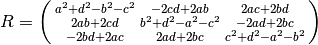
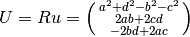
Quaternion  may be used to rotate the vector
  using
the matrix R:
using
the matrix R:
Thus, for  the default, non-rotated orientation, we
find
the default, non-rotated orientation, we
find  , the orientation estimate.
Now, considering a point passing through with orientation
given by  , we define a second point
  .
.
Given the camera matrix :
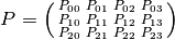
The image of point is  . Thus the vec on the image is
  .
.

Now, we need to shift coordinate system such that angles will be small
and thus reasonably approximated by normal distributions. We thus take
an expected orientation quaternion  and find the
expected image angle for that
and find the
expected image angle for that  :
:
We define our new observation model in this coordinate system:

Of course, if the original observation was  , the new
observation
, the new
observation  must also be placed in this coordinate system.

The EKF prior estimate of orientation is used as the expected
orientation , although is possible to use other values
for expected orientation.
Data association
The data association follows a very simple rule. An observation
 is used if and only if this value is close to the expected
value. Due to the definition of above, this is equivalent
to saying only small absolute values of are associated
with the target. This gating is established by the
is used if and only if this value is close to the expected
value. Due to the definition of above, this is equivalent
to saying only small absolute values of are associated
with the target. This gating is established by the
--gate-angle-threshold-degrees parameter to
flydra_analysis_orientation_ekf_fitter. --gate-angle-threshold-degrees
is defined between 0 and 180. The basic idea is that the program has a
prior estimate of orientation and angular velocity from past frames,
and any new 2D orientation is accepted or not (gated) based on whether
the acceptance makes sense – whether it’s close to the predicted
value. So a value of zero means reject everything and 180 means accept
everything. 10 means that you believe your prior estimates and only
accept close observations, where as 170 means you think the prior is
less reliable than the observation. (IIRC, the presence or absence of
the green line in the videos indicates whether the 2D orientation was
gated in or out, respectively.)
--area-threshold-for-orientation lets you discard a point if the
area of the 2D detection is too low. Many spurious detections often
have really low area, so this is a good way to get rid of
them. However, the default of this value is zero, so I think when I
wrote the program I found it to be unnecessary.